Advanced Software Engineering
Software ReuseCS 530 -
Reference: Sommerville, Software Engineering, 10 ed., Chapter 15
The big picture
In most engineering disciplines, systems are designed by composing existing components that have been used in other systems. Software engineering has been more focused on original development but it is now recognized that to achieve better software, more quickly and at lower cost, we need a design process that is based on systematic software reuse. There has been a major switch to reuse-based development over the past 10 years.
Scale of software reuse:
- System reuse: Complete systems, which may include several application programs.
- Application reuse: An application may be reused either by incorporating it without change into other or by developing application families.
- Component reuse: Components of an application from sub-systems to single objects may be reused.
- Object and function reuse: Small-scale software components that implement a single well-defined object or function may be reused.
Benefits of software reuse:
- Accelerated development: Bringing a system to market as early as possible is often more important than overall development costs. Reusing software can speed up system production because both development and validation time may be reduced.
- Effective use of specialists: Instead of doing the same work over and over again, application specialists can develop reusable software that encapsulates their knowledge.
- Increased dependability: Reused software, which has been tried and tested in working systems, should be more dependable than new software. Its design and implementation faults should have been found and fixed.
- Lower development costs: Development costs are proportional to the size of the software being developed. Reusing software means that fewer lines of code have to be written.
- Reduced process risk: The cost of existing software is already known, whereas the costs of development are always a matter of judgment. This is an important factor for project management because it reduces the margin of error in project cost estimation. This is particularly true when relatively large software components such as subsystems are reused.
- Standards compliance: Some standards, such as user interface standards, can be implemented as a set of reusable components. For example, if menus in a user interface are implemented using reusable components, all applications present the same menu formats to users. The use of standard user interfaces improves dependability because users make fewer mistakes when presented with a familiar interface.
Problems with software reuse:
- Creating, maintaining, and using a component library: Populating a reusable component library and ensuring the software developers can use this library can be expensive. Development processes have to be adapted to ensure that the library is used.
- Finding, understanding, and adapting reusable components: Software components have to be discovered in a library, understood and, sometimes, adapted to work in a new environment. Engineers must be reasonably confident of finding a component in the library before they include a component search as part of their normal development process.
- Increased maintenance costs: If the source code of a reused software system or component is not available then maintenance costs may be higher because the reused elements of the system may become increasingly incompatible with system changes.
- Lack of tool support: Some software tools do not support development with reuse. It may be difficult or impossible to integrate these tools with a component library system. The software process assumed by these tools may not take reuse into account. This is particularly true for tools that support embedded systems engineering, less so for object-oriented development tools.
- Not-invented-here syndrome: Some software engineers prefer to rewrite components because they believe they can improve on them. This is partly to do with trust and partly to do with the fact that writing original software is seen as more challenging than reusing other people's software.
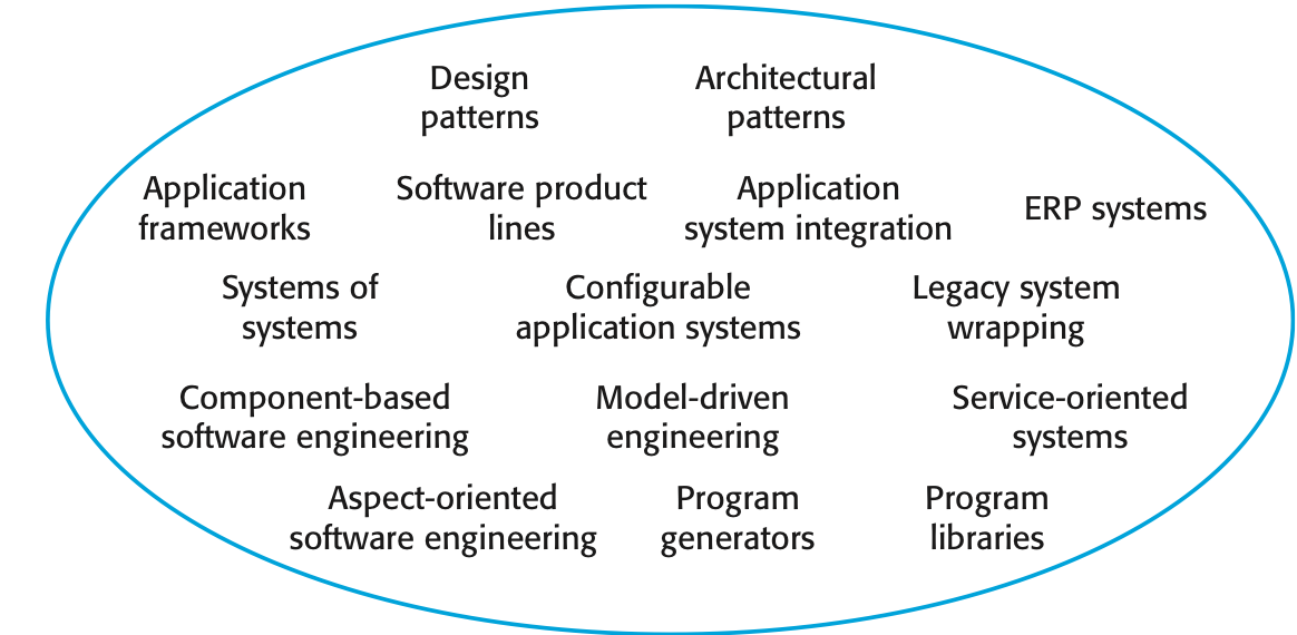
The reuse landscape
Although reuse is often simply thought of as the reuse of system components, there are many different approaches to reuse that may be used. Reuse is possible at a range of levels from simple functions to complete application systems. The reuse landscape covers the range of possible reuse techniques.
Key factors for reuse planning:
- The development schedule for the software.
- The expected software lifetime.
- The background, skills and experience of the development team.
- The criticality of the software and its non-functional requirements.
- The application domain.
- The execution platform for the software.
Application frameworks
Frameworks are moderately large entities that can be reused. They are somewhere between system and component reuse. Frameworks are a sub-system design made up of a collection of abstract and concrete classes and the interfaces between them. The sub-system is implemented by adding components to fill in parts of the design and by instantiating the abstract classes in the framework.
Application frameworks are moderately large entities that can be reused. They are somewhere between system and component reuse. Frameworks are a sub-system design made up of a collection of abstract and concrete classes and the interfaces between them. The sub-system is implemented by adding components to fill in parts of the design and by instantiating the abstract classes in the framework.
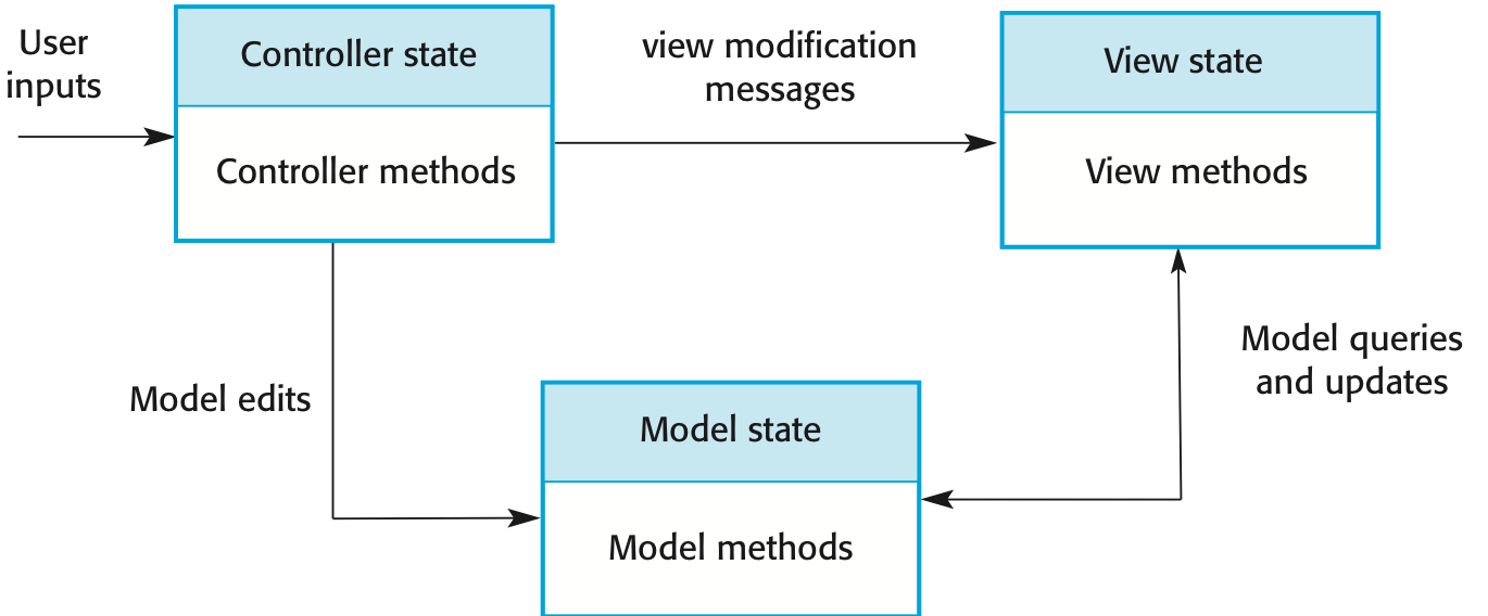
Web application frameworks (WAF) support the construction of dynamic websites as a front-end for web applications. WAFs are now available for all of the commonly used web programming languages e.g. Java, Python, Ruby, etc. Interaction model is based on the Model-View-Controller composite design pattern. An MVC framework supports the presentation of data in different ways and allows interaction with each of these presentations. When the data is modified through one of the presentations, the system model is changed and the controllers associated with each view update their presentation.
WAF features:
- Security: WAFs may include classes to help implement user authentication (login) and access.
- Dynamic web pages: Classes are provided to help you define web page templates and to populate these dynamically from the system database.
- Database support: The framework may provide classes that provide an abstract interface to different databases.
- Session management: Classes to create and manage sessions (a number of interactions with the system by a user) are usually part of a WAF.
- User interaction: Most web frameworks now provide AJAX support, which allows more interactive web pages to be created.
Frameworks are generic and are extended to create a more specific application or sub-system. They provide a skeleton architecture for the system. Extending the framework involves Adding concrete classes that inherit operations from abstract classes in the framework; Adding methods that are called in response to events that are recognized by the framework. Problem with frameworks is their complexity which means that it takes a long time to use them effectively.
Software product lines
Software product lines or application families are applications with generic functionality that can be adapted and configured for use in a specific context. A software product line is a set of applications with a common architecture and shared components, with each application specialized to reflect different requirements. Examples: a mobile operating system that works on different hardware models, a software line for a family of printers with varying features. Adaptation of a software line may involve:
- Component and system configuration;
- Adding new components to the system;
- Selecting from a library of existing components;
- Modifying components to meet new requirements.
The base application of a software product line includes:
- Core components that provide infrastructure support. These are not usually modified when developing a new instance of the product line.
- Configurable components that may be modified and configured to specialize them to a new application. Sometimes, it is possible to reconfigure these components without changing their code by using a built-in component configuration language.
- Specialized, domain-specific components some or all of which may be replaced when a new instance of a product line is created.
Application frameworks vs product lines:
- Application frameworks rely on object-oriented features such as polymorphism to implement extensions. Product lines need not be object-oriented (e.g. embedded software for a mobile phone)
- Application frameworks focus on providing technical rather than domain-specific support. Product lines embed domain and platform information.
- Product lines often control applications for equipment.
- Software product lines are made up of a family of applications, usually owned by the same organization.
Product line architectures must be structured in such a way to separate different sub-systems and to allow them to be modified. The architecture should also separate entities and their descriptions and the higher levels in the system access entities through descriptions rather than directly.
Various types of specialization of a software product line may be developed:
- Different versions of the application are developed for different platforms.
- Different versions of the application are created to handle different operating environments e.g. different types of communication equipment.
- Different versions of the application are created for customers with different functional requirements.
- Different versions of the application are created to support different business processes.
Software product lines are designed to be reconfigurable. This configuration may occur at different stages in the development process:
- Design time configuration: The organization that is developing the software modifies a common product line core by developing, selecting or adapting components to create a new system for a customer.
- Deployment time configuration: A generic system is designed for configuration by a customer or consultants working with the customer. Knowledge of the customer's specific requirements and the system's operating environment is embedded in configuration data that are used by the generic system.
Application system reuse
An application system product is a software system that can be adapted for different customers without changing the source code of the system. Application systems have generic features and so can be used/reused in different environments. Application system products are adapted by using built-in configuration mechanisms that allow the functionality of the system to be tailored to specific customer needs.
Benefits of application system reuse:
- As with other types of reuse, more rapid deployment of a reliable system may be possible.
- It is possible to see what functionality is provided by the applications and so it is easier to judge whether or not they are likely to be suitable.
- Some development risks are avoided by using existing software. However, this approach has its own risks, as I discuss below.
- Businesses can focus on their core activity without having to devote a lot of resources to IT systems development.
- As operating platforms evolve, technology updates may be simplified as these are the responsibility of the COTS product vendor rather than the customer.
Problems of application system reuse:
- Requirements usually have to be adapted to reflect the functionality and mode of operation of the COTS product.
- The COTS product may be based on assumptions that are practically impossible to change.
- Choosing the right COTS system for an enterprise can be a difficult process, especially as many COTS products are not well documented.
- There may be a lack of local expertise to support systems development.
- The COTS product vendor controls system support and evolution.
Configurable application systems are generic application systems that may be designed to support a particular business type, business activity or, sometimes, a complete business enterprise. For example, an application system may be produced for dentists that handles appointments, dental records, patient recall, etc. Domain-specific systems, such as systems to support a business function (e.g. document management) provide functionality that is likely to be required by a range of potential users.
An Enterprise Resource Planning (ERP) system is a generic system that supports common business processes such as ordering and invoicing, manufacturing, etc. These are very widely used in large companies - they represent probably the most common form of software reuse. The generic core is adapted by including modules and by incorporating knowledge of business processes and rules. A number of modules to support different business functions. A defined set of business processes, associated with each module, which relate to activities in that module. A common database that maintains information about all related business functions. A set of business rules that apply to all data in the database.

Key elements of an ERP system architecture:
- A number of modules to support different business functions.
- A defined set of business processes, associated with each module, which relate to activities in that module.
- A common database that maintains information about all related business functions.
- A set of business rules that apply to all data in the database.
An ERP system configuration usually involves:
- Selecting the required functionality from the system.
- Establishing a data model that defines how the organization's data will be structured in the system database.
- Defining business rules that apply to that data.
- Defining the expected interactions with external systems.
- Designing the input forms and the output reports generated by the system.
- Designing new business processes that conform to the underlying process model supported by the system.
- Setting parameters that define how the system is deployed on its underlying platform.
Integrated application systems
Integrated application systems are applications that include two or more application system products and/or legacy application systems. You may use this approach when there is no single application system that meets all of your needs or when you wish to integrate a new application system with systems that you already use. To develop integrated application systems, you have to make a number of design choices:
- Which individual application systems offer the most appropriate functionality? Typically, there will be several application system products available, which can be combined in different ways.
- How will data be exchanged? Different products normally use unique data structures and formats. You have to write adaptors that convert from one representation to another.
- What features of a product will actually be used? Individual application systems may include more functionality than you need and functionality may be duplicated across different products.
Application system integration can be simplified if a service-oriented approach is used. A service-oriented approach means allowing access to the application system's functionality through a standard service interface, with a service for each discrete unit of functionality. Some applications may offer a service interface but, sometimes, this service interface has to be implemented by the system integrator. You have to program a wrapper that hides the application and provides externally visible services.
Application system integration problems:
- Lack of control over functionality and performance: application systems may be less effective than they appear
- Problems with application system inter-operability: different application systems may make different assumptions that means integration is difficult
- No control over system evolution: application system vendors not system users control evolution
- Support from system vendors: application system vendors may not offer support over the lifetime of the product